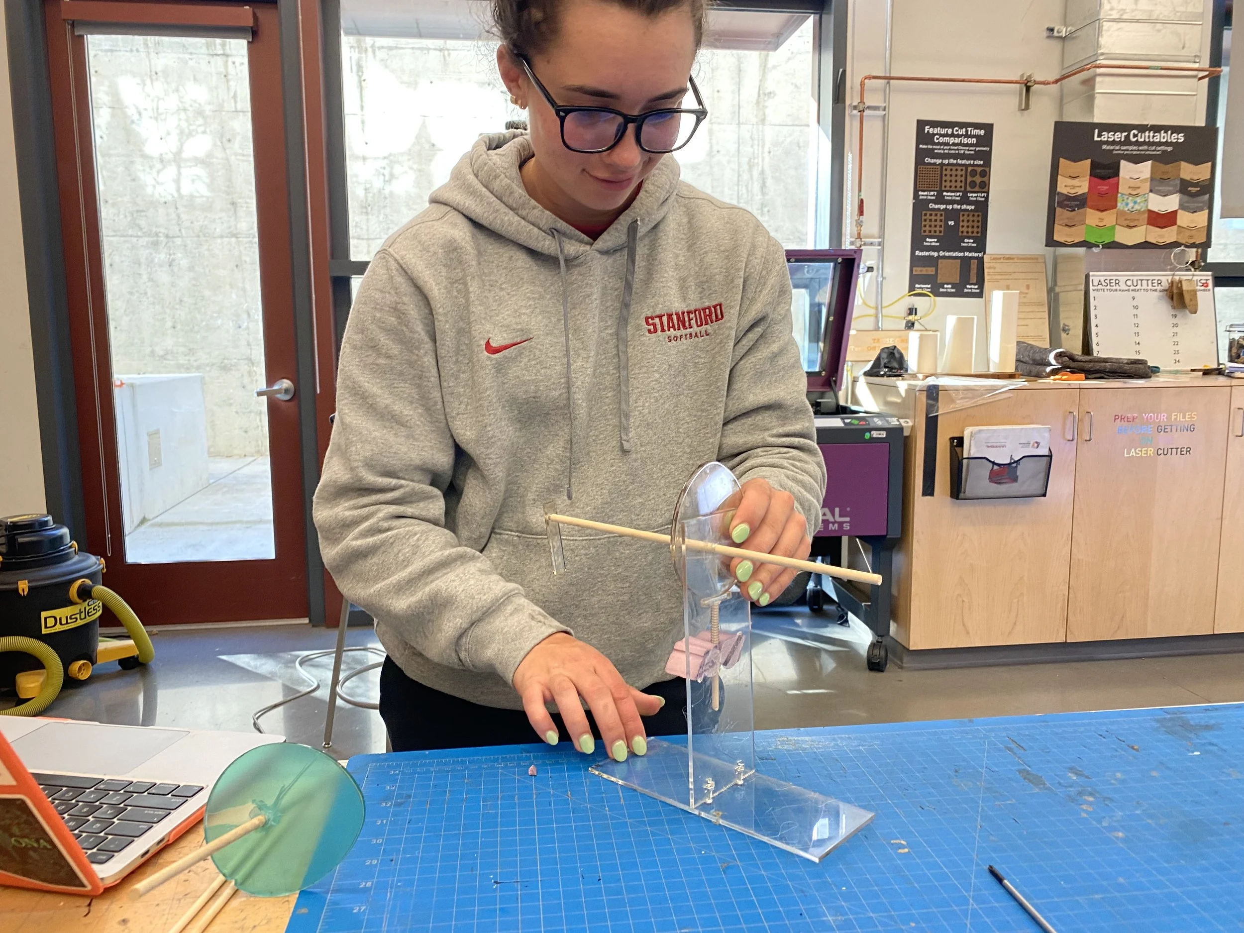
Universal Stamp Machine
For: Stanford University
Class: ME 102 - Foundations of Product Realization - Fall 2022
Length: 4 Weeks
Materials: 3D Printed PLA, Hardware, Acrylic, Extension Spring
Skills: CAD/Fusion 360, Laser Cutting, 3D Printing, Hardware Assembly, Iterative and Rapid Prototyping, Performance Testing
Type: Individual Project
Key Requirements:
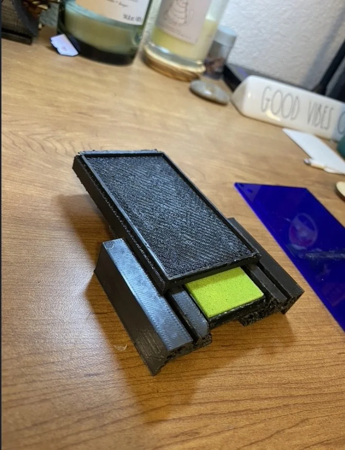
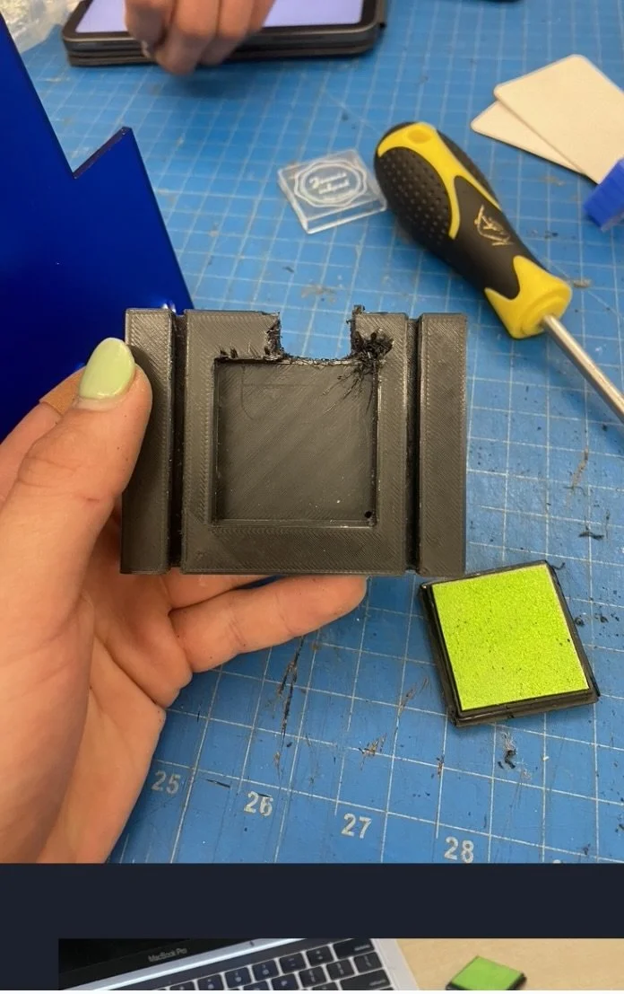
One integrated device (except stamp & ink pad, which are removable)
Rotary input (knob/lever) → linear stamp travel ≥ 2"
Uses stock mechanical hardware (shafts, bushings, bearings) and one spring (compression or extension) in linear load
Prints consistently in same position on a 3.5" × 2" business card
Ink pad contacts only the stamp, stays in receptacle throughout cycle
Machine is freestanding, operable one-handed, serviceable, and mechanism is visible
Materials: acrylic, plywood, 3D prints
Fits within ~10" × 4" × 8"
$40 budget
Deliverables:
Fully functioning machine meeting all specs
One-sheet pictorial instructions
Photo essay (20–25 slides) documenting process: sketches, prototyping, CAD, BOM, testing, reflection
In-person final presentation
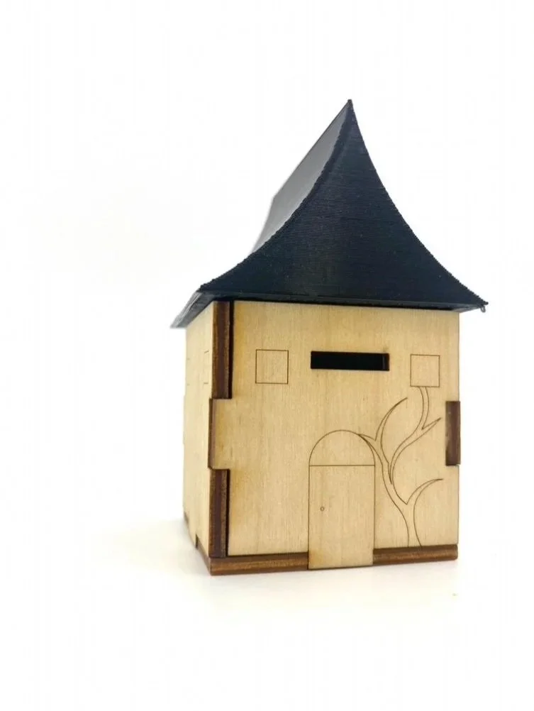
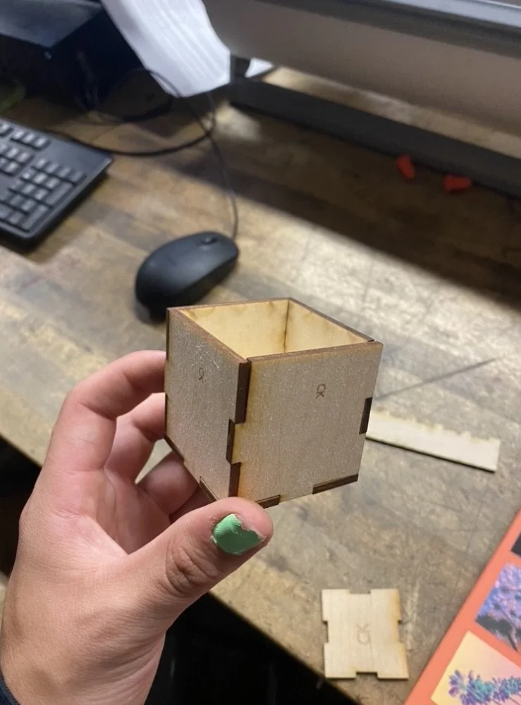
Context
Throughout the quarter, we learned how to model and sketch objects in CAD, create friction-fit joints in plywood, and design 3D-printed parts that achieve precise friction fits

Inspiration and Concept Sketches
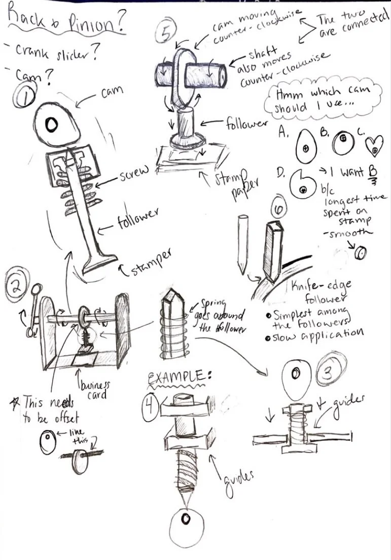
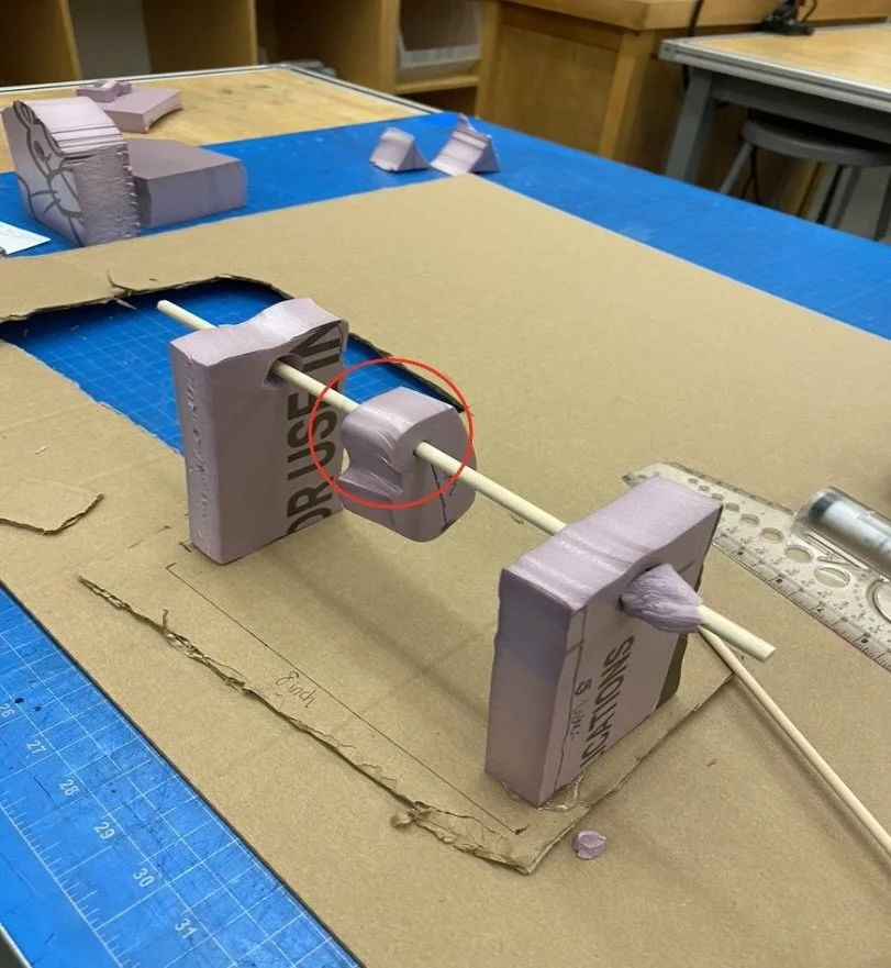
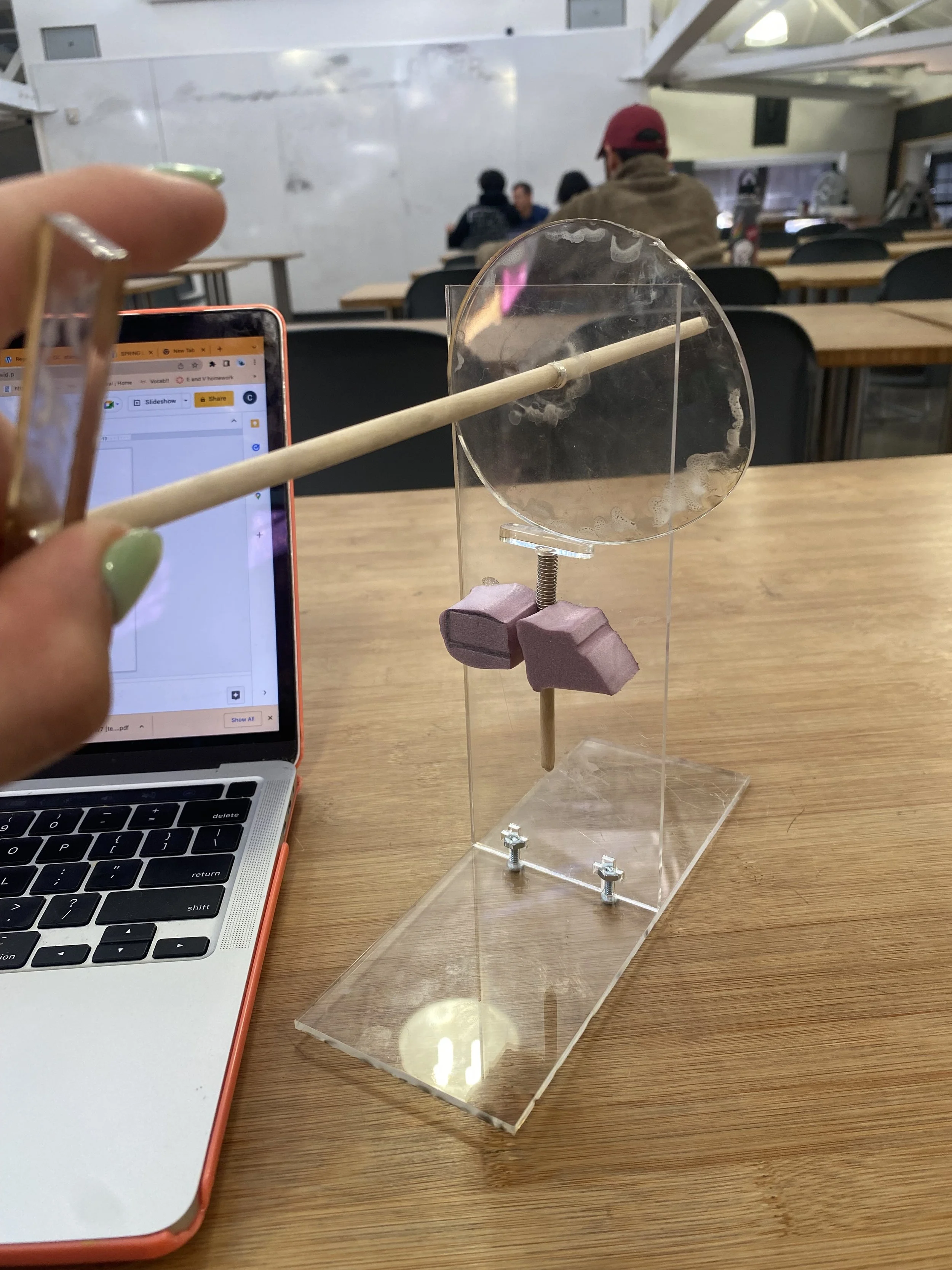
Prototype 1: Cam-&-Shaft
Driver and Metrics for Success: Prototype 1
Driver Question: What kind of cam will be able to successfully allow the follower to slide along its surface without stopping or moving out of place?
Metrics for success:
Does the follower move a lot and get pulled out of place by the rotation of the cam?
Does the follower stay parellel to the cam?
Does the follower stay on top of the cam?
Does the follower catch on the cam and get stuck?
Results:
I enjoyed this quick-build prototype, which still required careful planning and sketching. It helped me refine part dimensions, ensure smooth cam-and-follower motion, and realize the spring—not gravity—should reset the stamp
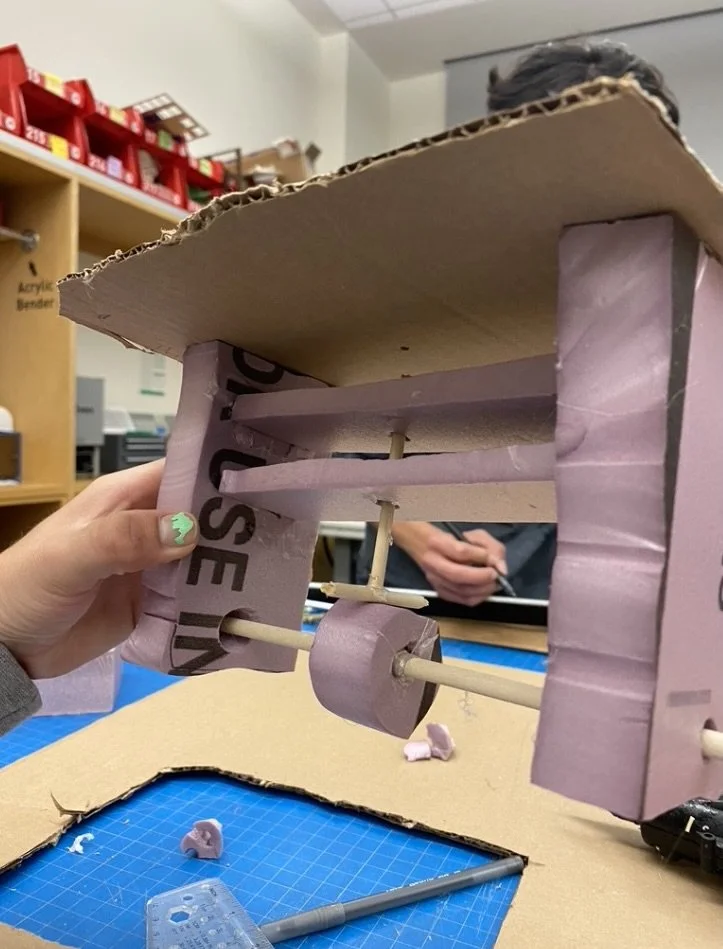
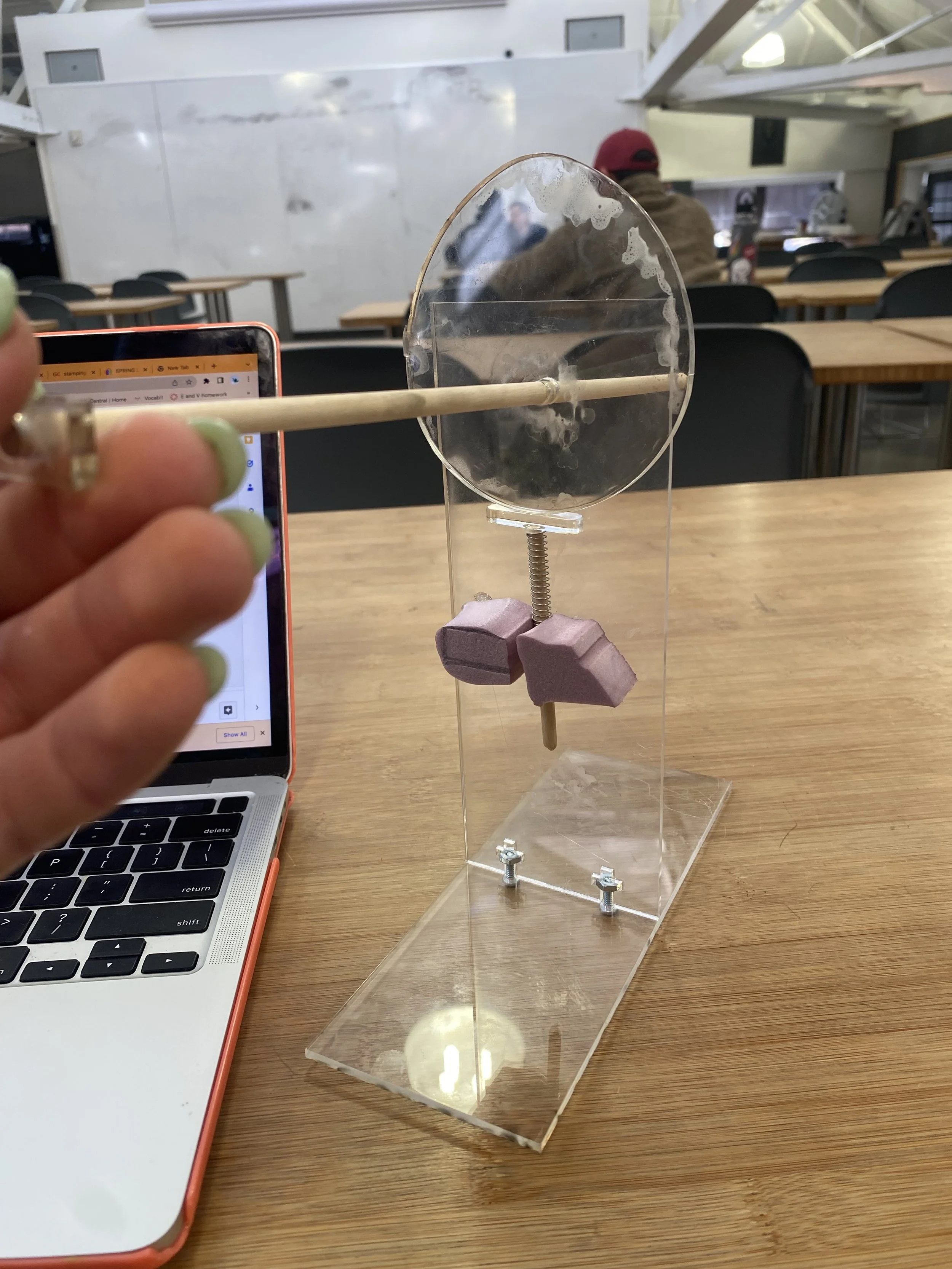
Prototype 2: Cam-&-Shaft 2.0
Driver and Metrics for Success: Prototype 2
Driver Question: What is the ideal shape/height to width ratio of the cam so that the follower and shaft attached smoothly run against it and does not get stuck?
Metrics for success:
Does the shaft get stuck on the cam?
Can the cam rotate in a smooth motion?
Can I work the lever with one hand?
Does the follower stay in contact with the cam the entire time? Resu
Results:
Laser cutting a larger cam and adding a longer acrylic follower allowed the rotary motion to push the shaft down as intended. However, since the compression spring could only compress one inch—and my final design required two inches of travel—I realized I’d need a different mechanism. This prototype also gave me valuable insights into creating proper T-slots
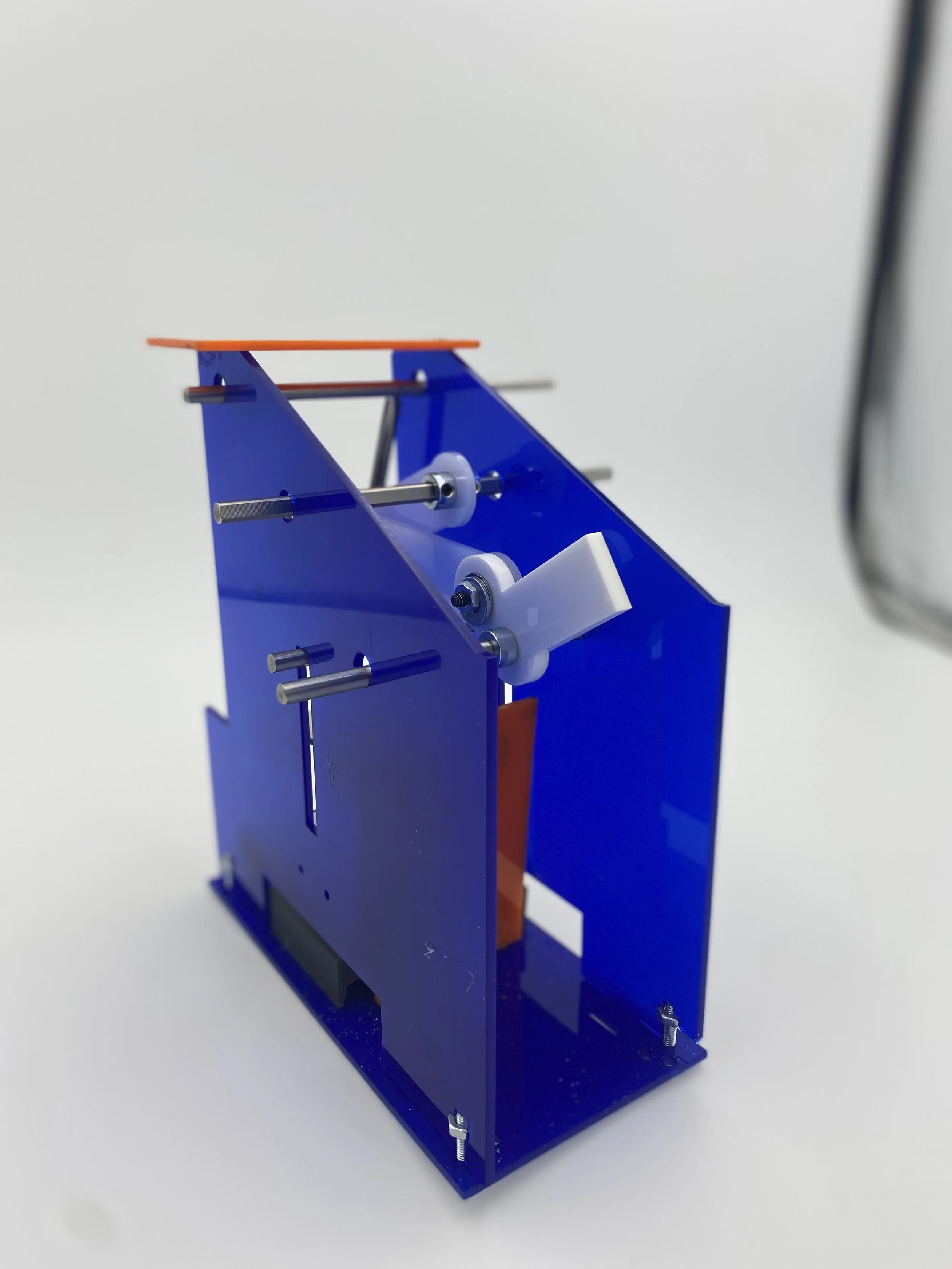
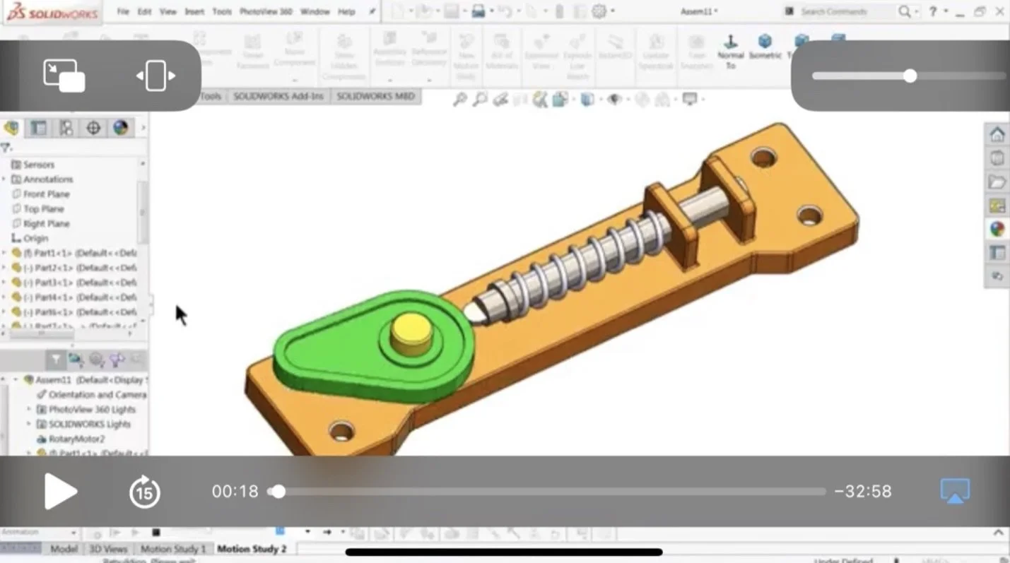
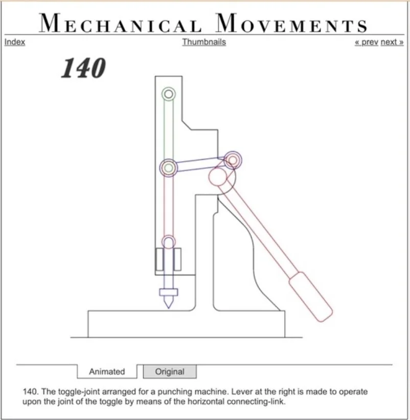
Prototype 3: Toggle Joint Linkage
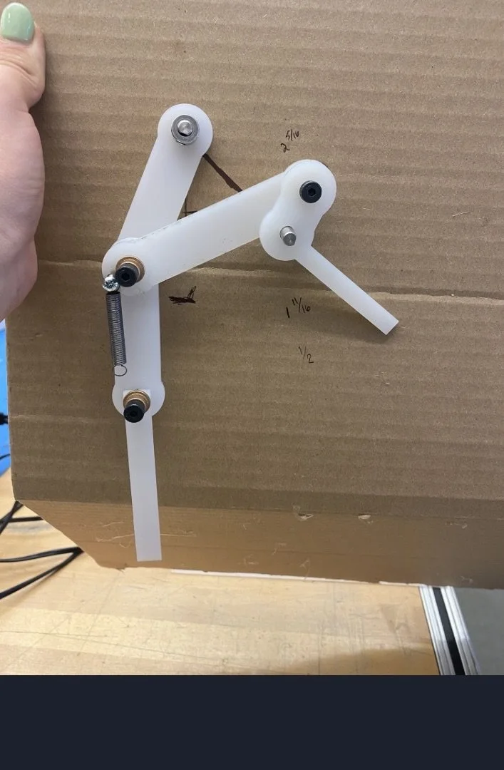
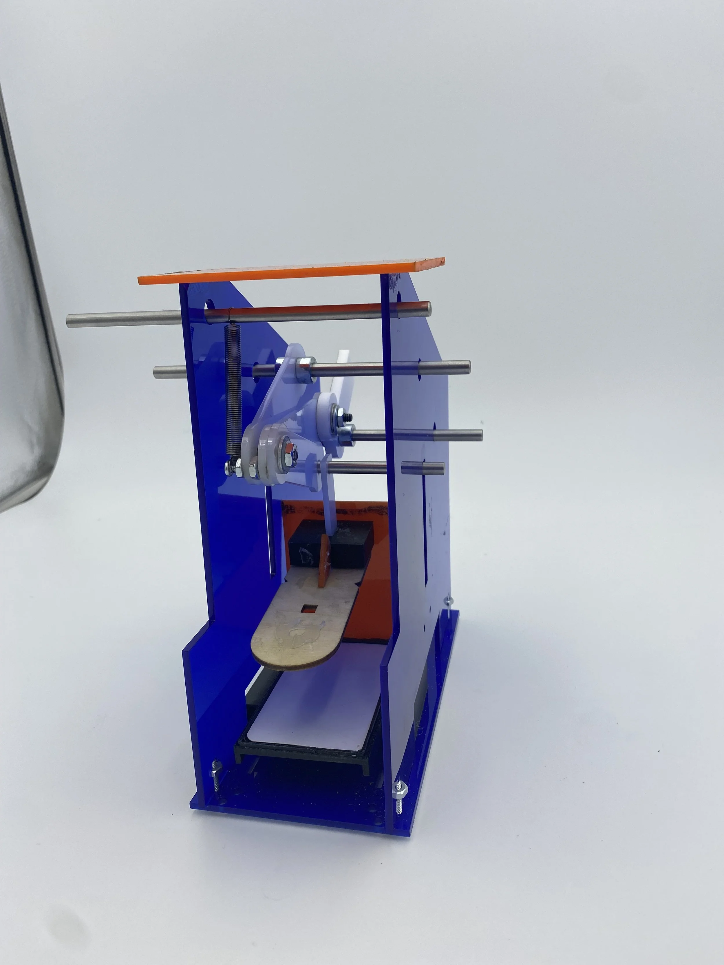
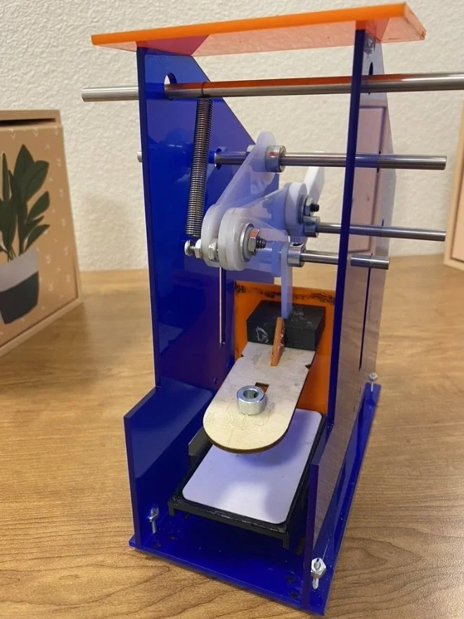
I decided to move forward with my final prototype, switching from the cam-and-shaft model to an extension spring with a toggle-joint mechanism. I had a clearer understanding of how to design and assemble the linkages and how the motion would work, whereas with the cam-and-shaft design, I couldn’t solve how to achieve the required 2-inch stamp travel using a compression spring that could only compress 1 inch.
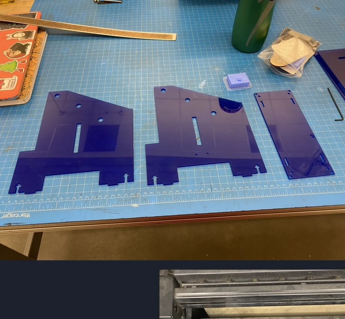
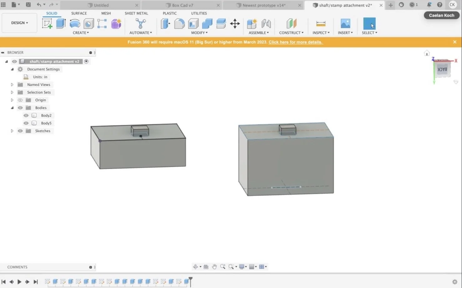
3D Printing and Laser Cutting
Constraining Parts to Same Plane
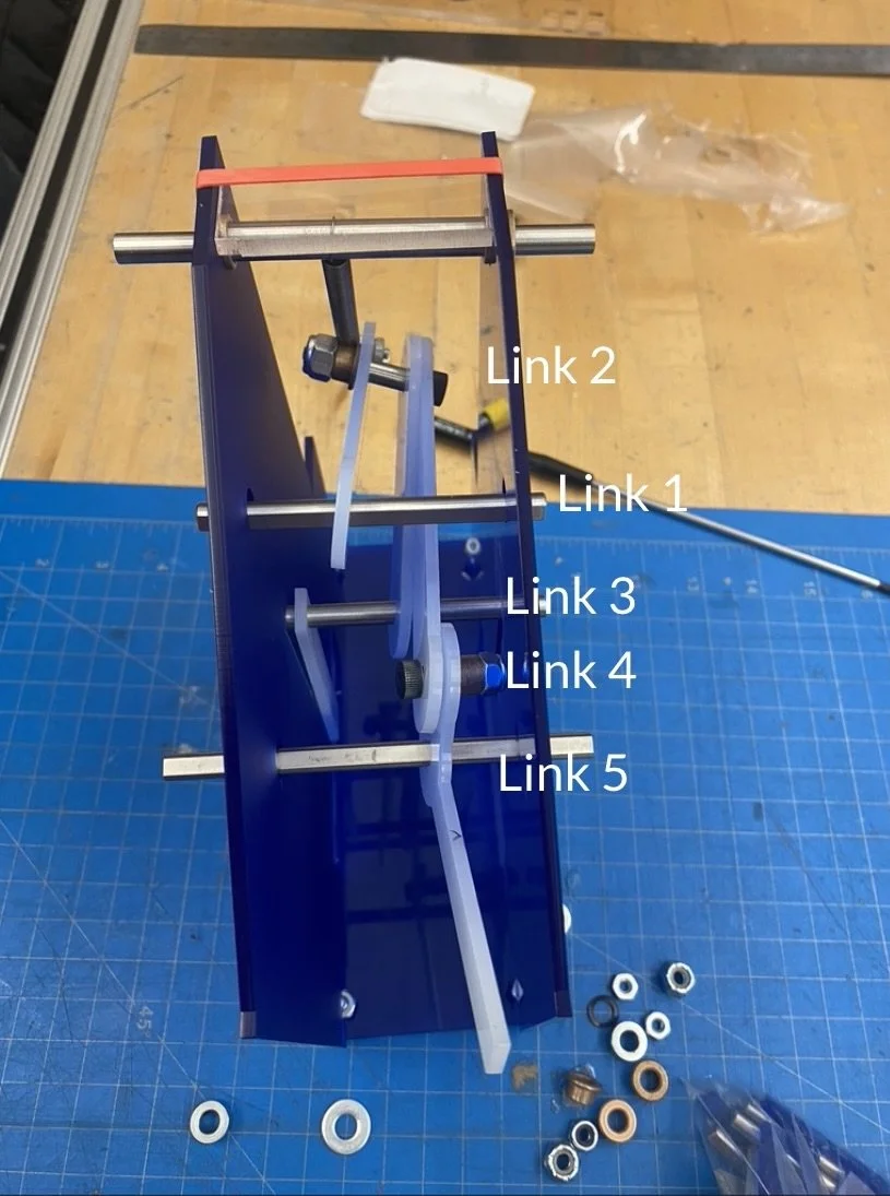
Driver and Metrics for Success: Prototype 3
Driver Question: What range of distances can the joints of the bars be from one another so that the rotary motion still allows the bars to move and for the bottom joint to move down 2 inches?
Metrics for Success:
Does the bottom joint move down 2 inches?
Is the motion of the joints smooth/functional?
Do the d-shafts supporting the joints stay in place?
Does the spring not over-extend?
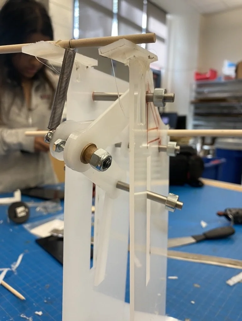
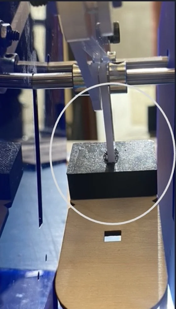
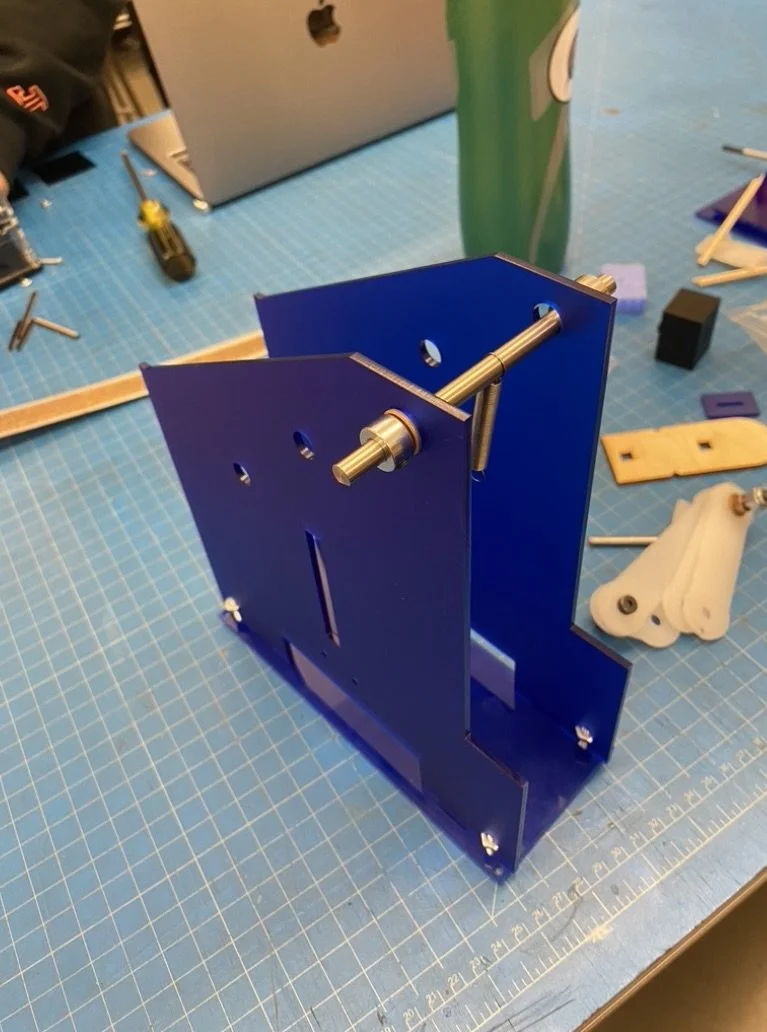
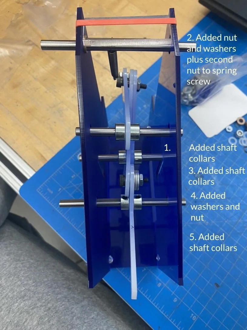
Results:
I used the drill press to make holes in the acrylic and an electric saw to quickly cut the walls and base. This prototype worked well, delivering the 2 inches of linear motion I needed. It showed me the importance of keeping joints in the same plane, minimizing horizontal movement, and confirmed that positioning the extension spring higher than the joints for reset motion was a good idea for the final build. I also realized I needed a stabilizer to guide the stamp’s downward movement.
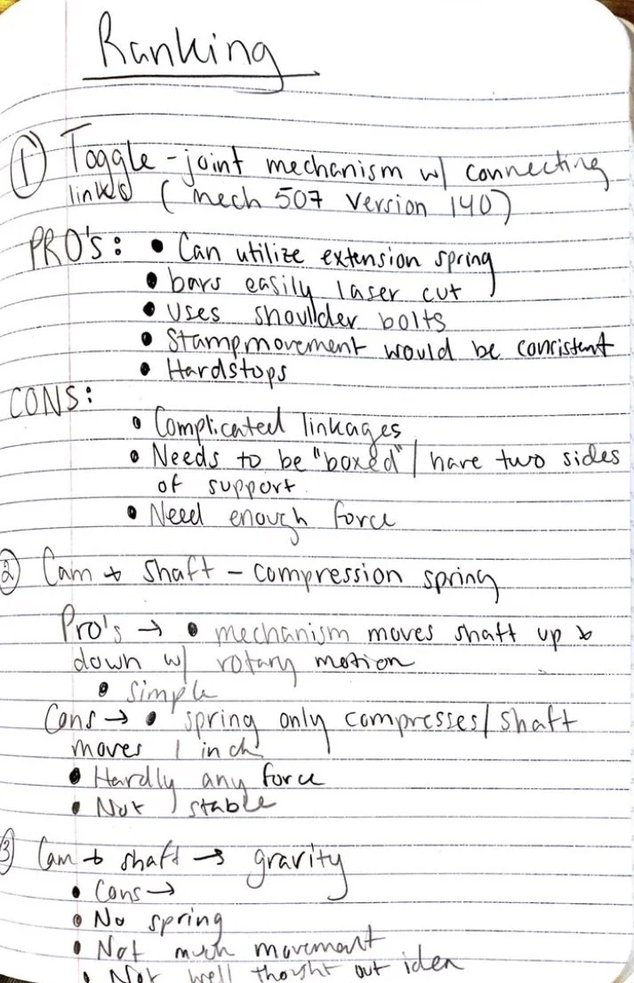
Ranking/Decision Tree
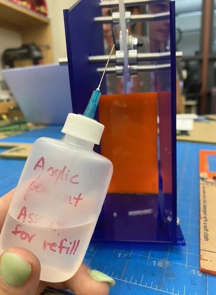
Final Steps
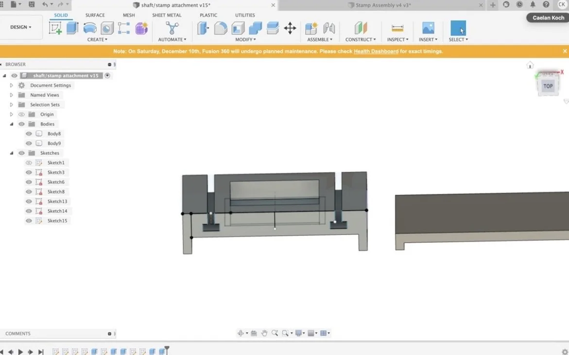
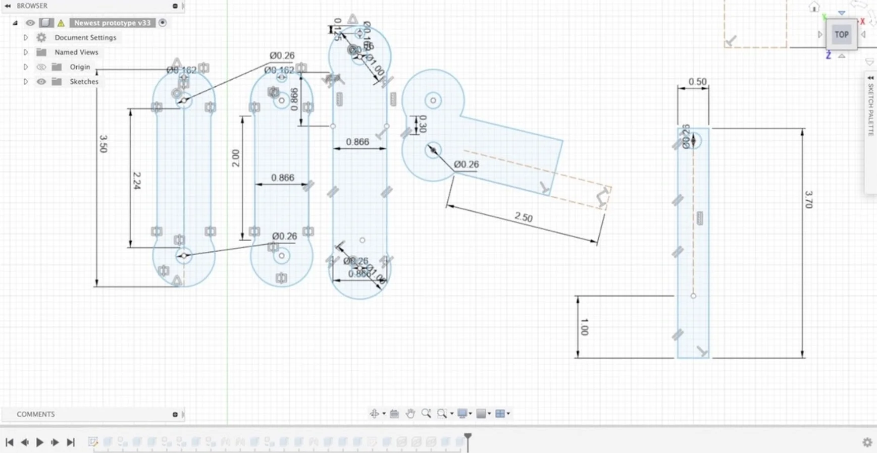
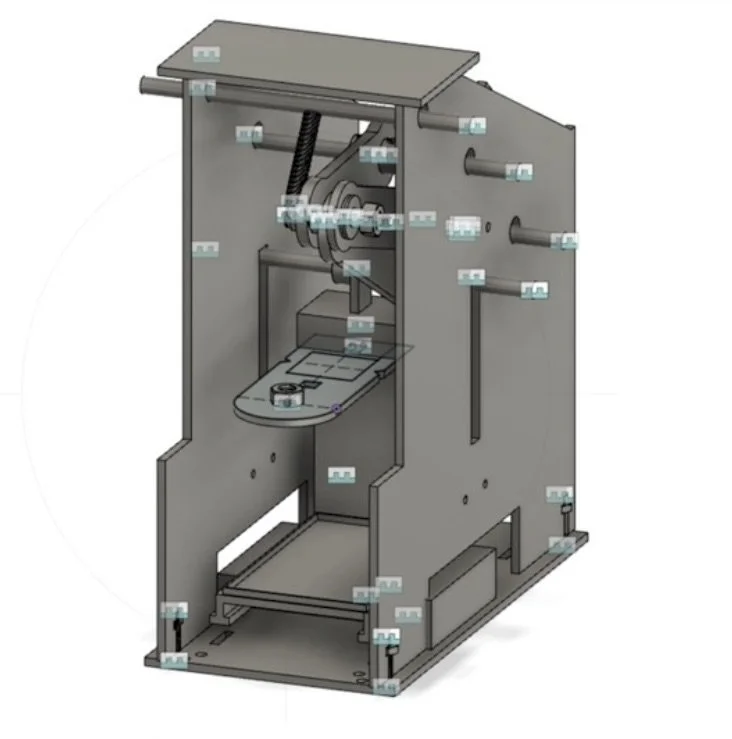
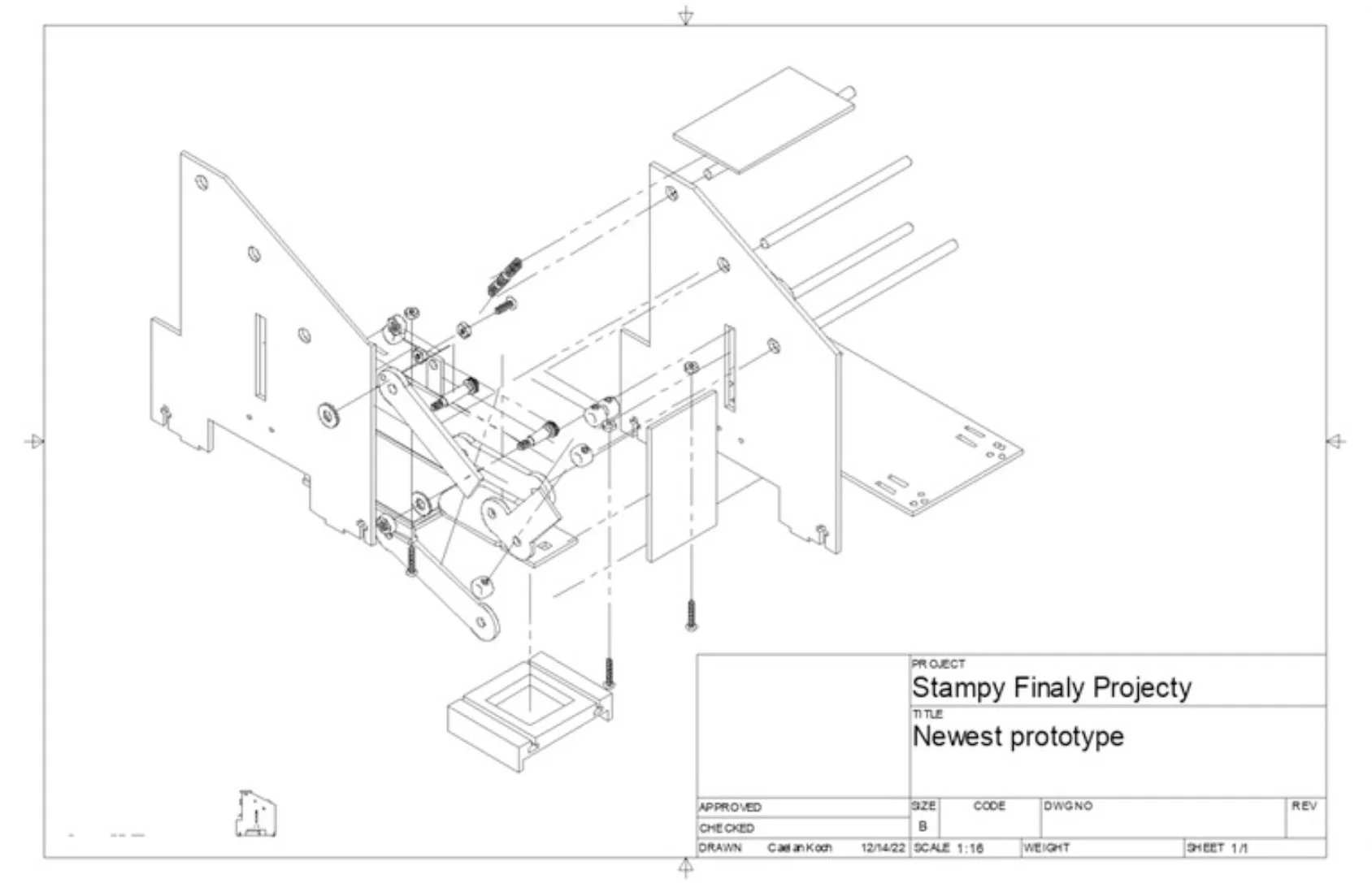
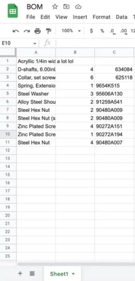
CAD, Exploded View of Assembly, BOM
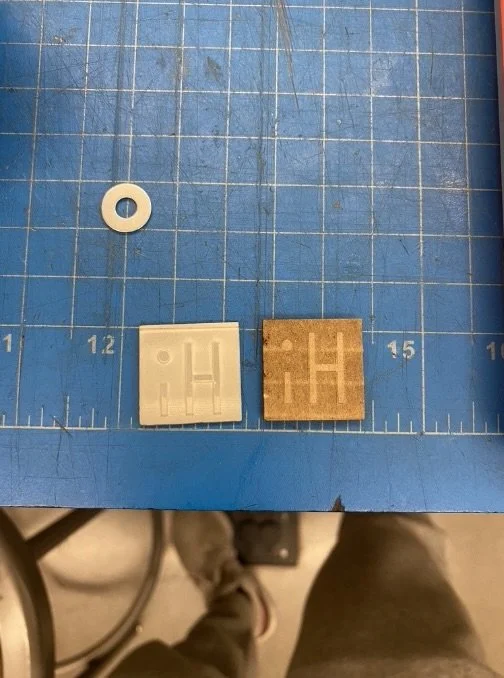
Results and Reflection
The stamp prints faintly, and widening the base of my 3D parts made the placement on the card less consistent. Still, I’m proud of the time, effort, and progress I put in. I learned the importance of precise math for 3D-printed dimensions to avoid reprints or modifications, as well as breaking a complex build into clear steps to stay on track. Even if the machine isn’t perfect, I value both what I accomplished and what I learned.